
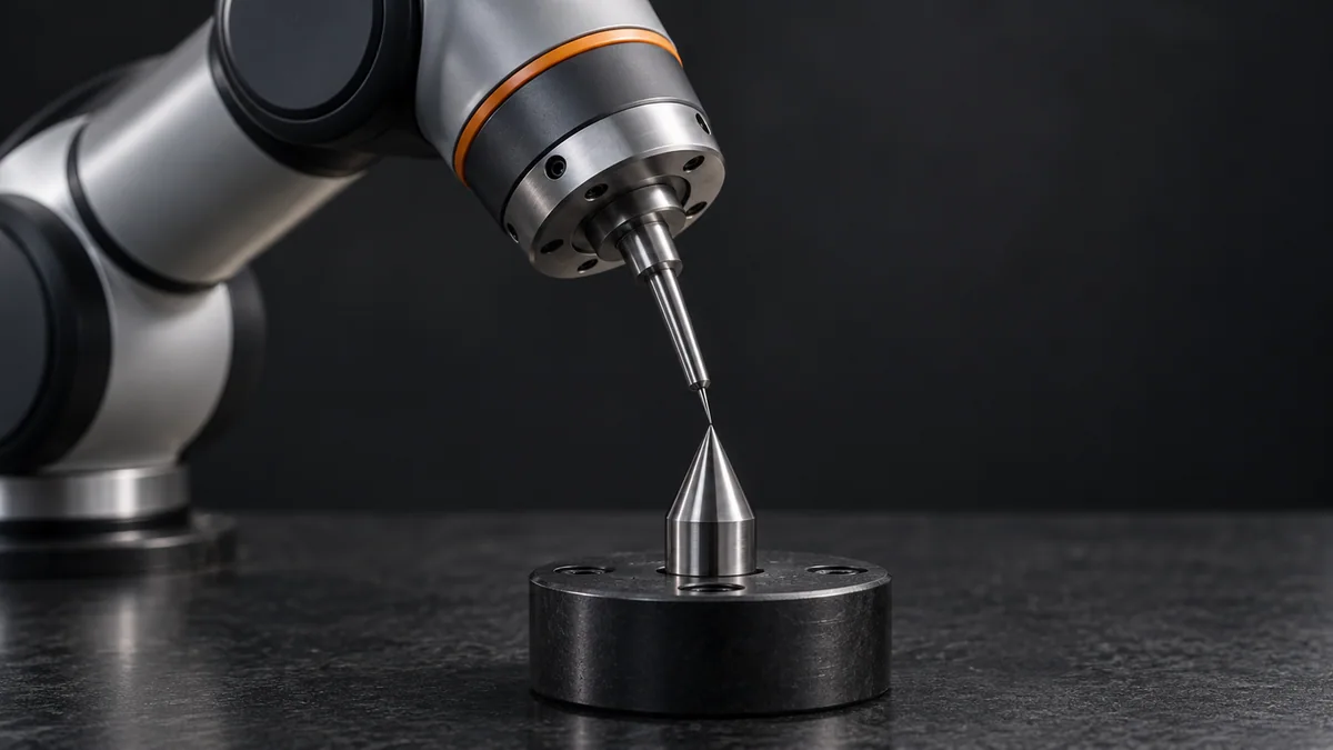
What you need
Use the controller’s documented TCP teaching method and a suitable fixed reference. Begin with a simulator or supervised reduced-speed setup.
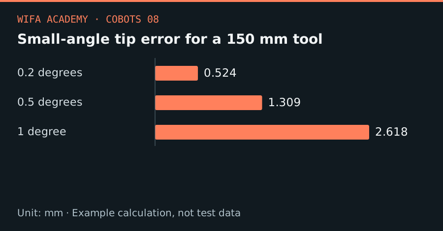
Read the diagram as a data table
| Condition or component | mm |
|---|---|
| 0.2 degrees | 0.524 |
| 0.5 degrees | 1.309 |
| 1 degree | 2.618 |
The calculation
e ≈ L × δθ
For a small angle, e is lateral error in mm, L is tool length in mm, and δθ is orientation error in radians.
Worked example
A 150 mm tool with a 1° orientation error has an approximate lateral error of 150×π/180 = 2.62 mm. At 0.2° the error is about 0.52 mm. This is geometric sensitivity, not a robot accuracy specification.
Try it step by step
- Inspect tool mounting and looseness before calibration; a moving mechanical reference cannot be corrected with a saved offset.
- Follow the manufacturer’s multi-orientation TCP procedure and use sufficiently different wrist poses to make the geometry informative.
- Validate the result at additional orientations not used for teaching, approaching the reference under the specified safe setup.
- Save the tool definition with its mounting revision and revalidate after changing fingers, adapters or the tool itself.
How to check the result
Plot measured tip displacement against wrist orientation. A repeating orientation-dependent pattern suggests a TCP or orientation definition problem.
Common mistake to avoid
Degrees must be converted to radians in the approximation. A position-only TCP calibration does not automatically establish the correct tool-axis direction.
Reference reading
Primary references for the underlying models, APIs or application context. The worked numbers and plots above are educational calculations, not results reported by these sources.


